Table of Contents
Lab 3
In this exercise, let's build a microphone preamp on the protoboard, acquire the audio signals on the ATmega328P using the ADC, process the auditory signal to measure the RMS power (sound volume), and then use the average sound volume over the past few hundred ms of time to set the position of a servo motor. In lab_4 you will turn your prototype into a PCB schematic.
To achieve this, we need to interface to and control a servo motor and build a microphone preamplifier. Let's use the protoboard for both of these.
Steps for this exercise
If you finally have to give up for lack of time or success, a solution will be revealed in two weeks. Follow the following general steps to complete this exercise:
- Build the microphone preamplifier on the solderless breadboard to amplifier the microphone signal. One person can do this while the others in a group can work on the next parts.
- Sketch an outline (flow diagram) of your application, including the AD conversion, the servo control, the signal processing. What peripherals from ATmega328P will you need?
- Start a new Arduino project.
- Use the Servo library to write your own PWM code to control the servo.
- Use analogRead() function that uses the ADC to read the microphone preamp output.
- Write the DSP (digital signal processing) code to process the ADC samples to control the servo position.
- Use Serial from Arduino Reference Language to debug your code.
- Document your code with comments.
- Demonstrate your working system to Tobi and send your project by zip (or .7z) archive attachment email to Tobi Delbruck.
Background information
- uc - arduino for microcontroller software tools and example firmware setup
- servos - information about RC hobby servo motors
- microphones - information about electret microphones
- breadboard - solderless breadboard
- micpreamp - microphone preamplifier
Starting Arduino Project
The easiest way to start is to open from the File menu a basic example and use it as a template, like the 01-Basic⇒Blink.
Let's modify this sketch so that we produce a suitable servo output signal in response to the sampled sounds from the ADC.
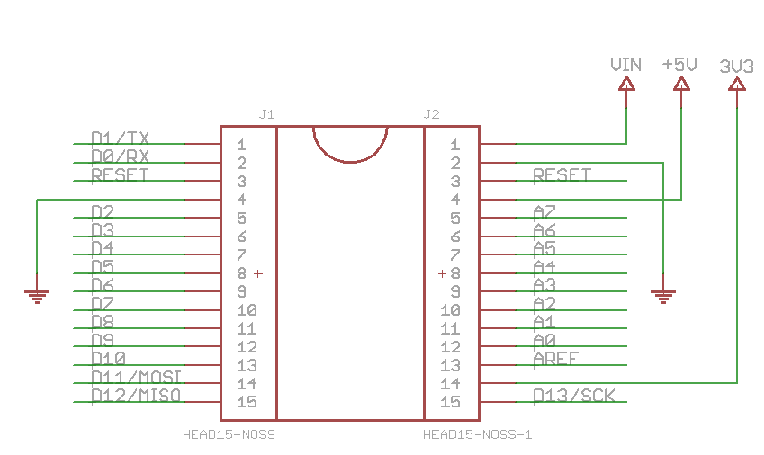
Arduino Nano v3.0 board pin headers
PWM - Pulse Width Modulation
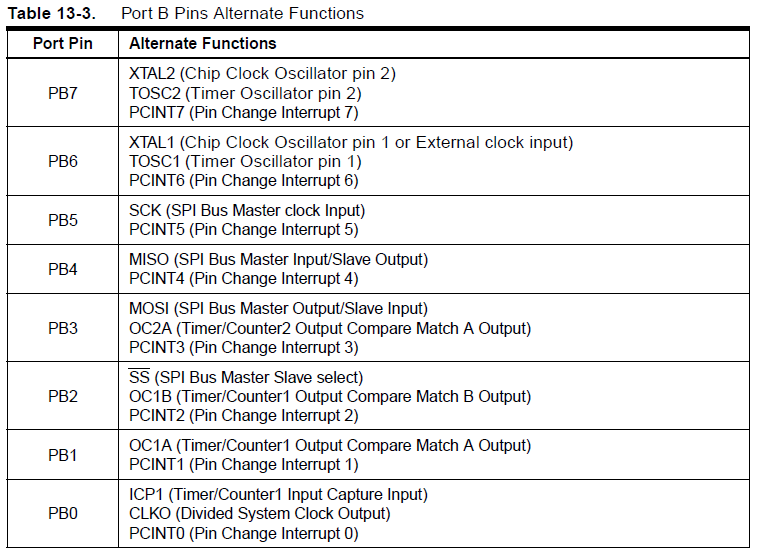
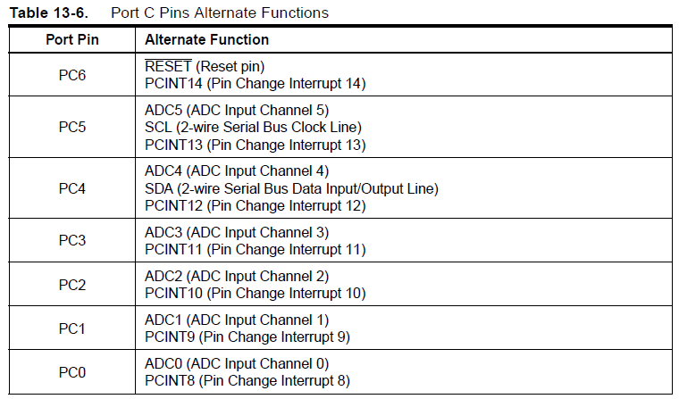
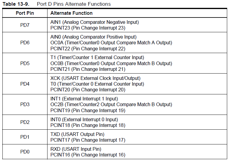
- Decide on a new PWM output pin for your servo output pulses. Looking at the Arduino Nano schematic and the ATmega328P datasheet, we see that the nano board hard-wires PB5 (D13) to the amber LED Anode, PD0 (D0) to UART RX signal, and PD1(D1) to UART TX signal. These are pins 17, 30 and 31 on the ATmega328P. If you look carefully in the datasheet you will find that not all digital pins of the Arduino Nano headers can be used. Figure out which Timer/Counter is used by Servo library and then select the proper pin.
Here you have a quick example of how to use Servo library:
#include<Servo.h>

int led = 13;
char i=0;
//You can instantiate a new variable of Servo type, that correspond to an object with several useful methods.
Servo myservo;
// the setup routine runs once when you press reset:
void setup() {
  // initialize the digital pin as an output.
  pinMode(led, INPUT);
  // initialize servo to be on pin D9, min high time of 1ms and max 2ms.
  myservo.attach(9,1000,2000);
  // start with a PWM signal of 20ms period (default value) and 1ms high time (0 degrees)
  myservo.write(0);
}

// the loop routine runs over and over again forever:
void loop() {
  delay(10);               // wait for a 10 milliseconds
  myservo.write(i%180);    // update PWM for servo controller with a new duty cycle (high time)
}
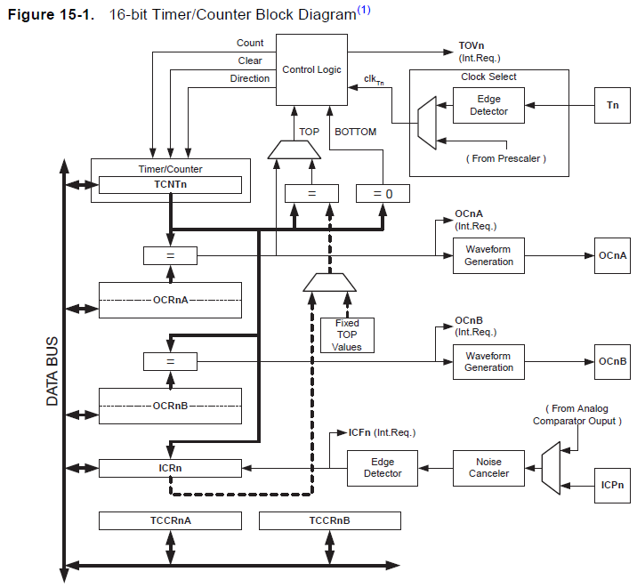
To see what this all means, look at the following block diagram, from the datasheet. There are three timers that can be used for generating up to 6 PWM signals, but for Servo control only Timer1 can be used because of the requirements of the PWM period signal of a servo. Each timer has two waveform generators (A and B). Depending on timer value and OCR1A or OCR1B register values the PWM signtal is generated. The Timer1 overflows the waveform generator reset signal output, and when Timer1 reach the value stored in OCR1x register, the waveform generator invert the state of the output signal.
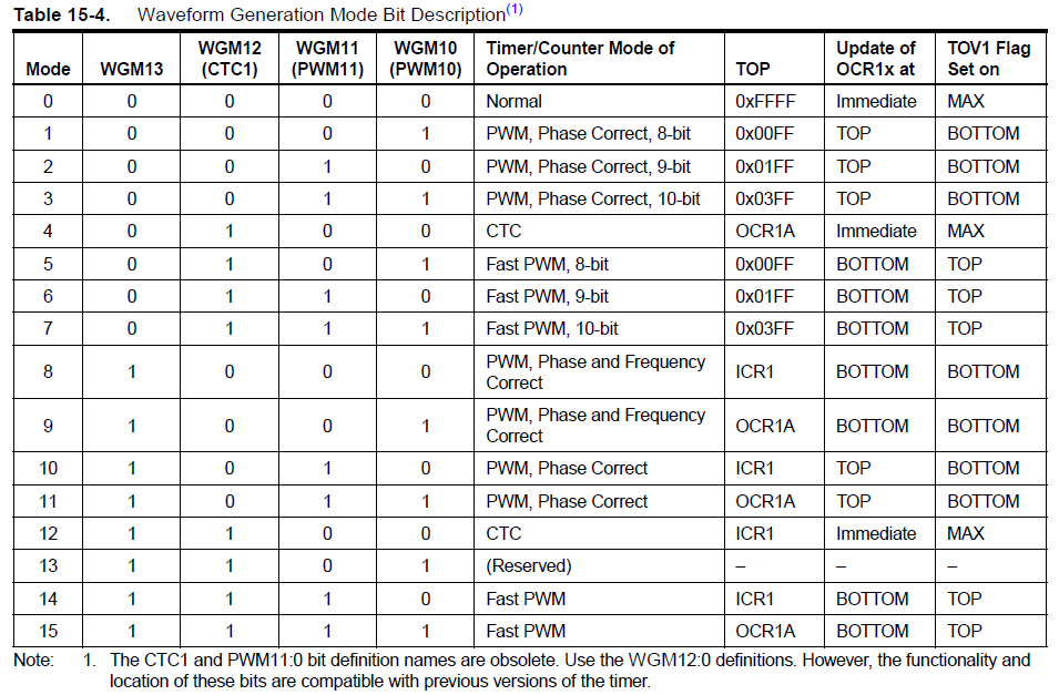
Timer1 clock source can come from outside (External pin T1) or it can be a prescaled clock from system clock circuitry of the microcontroller. Timer1 has several operating modes that allow different frequency resolutions on PWM signals. The counter can be used in one direction (once the TOP count is reached it changes to BOTTOM and starts again), or in two directions (from BOTTOM to TOP counting up and then from TOP to BOTTOM counting down, obtaining double resolution).
You can try it out with a servo motor, using the USB VBUS +5V to power the servo and a long pin header to connect to the protoboard and the servo, following the guide above according to your servo type. Use a 10000uF electrolytic capacitor and a blocking 1N4007 diode to bypass the VBUS to ground on the protoboard or you will get a huge amount of motor noise appearing in VBUS! You will end up with about 4V to power the servo which is on the low side but it should still work.
Sampling audio and signal processing
We've already built the microphone preamp circuit on the protoboard, using a JEFT microphone (datasheet), resistors, capacitors, and an LM324N quad opamp.
Now let's write a main loop that samples the microphone input, computes the average mean square sound level, low pass filters it, and sets the servo according to this sound volume. Ideally you would sample at a regular rate set by a timer interrupt. Remember that Timer1 is already in use by PWM generator and that Timer0 is used by some internal Arduino functions (like delay one), so let's use remaining timer to manage a correct sample rate for the ADC, Timer2. In order to manage easily Timer2, you can download MsTimer2 library and install it on the Arduino/libraries folder unziping this zip file there. Every time you install a new library in the libraries folder you must restart Arduino software. Then you can use it in your code like in this example:
#include <MsTimer2.h>
// the setup routine runs once when you press reset:
void setup() {
  // initialize timer2 overflow and a function to be call during ISR.
  MsTimer2::set(1000,t2_ovf);
  MsTimer2::start();
}
// the loop routine runs over and over again forever:
void loop() {
   //wait for ADC value and process it using DSP chain.
}

void t2_ovf()
{
  //do something like set a FLAG for the loop for reading the ADC
}
The pseudo code for the signal processing should go as follows:
- Get an ADC sample
- Update the fading average sample value. We need to subtract this from the sample to get the deviation from the mean.
- Compute the square of the difference of the sample from the fading average.
- Update the fading average mean square value.
- Use this value to set the servo position.
Remember that you only have fixed point hardware. The ADC samples are 10 bits expressed as the 10 lsbs of a int value. You can add several of 10 bit values in a 16 bit value, or you can move to a long variable
Debugging by GPIO toggling
You use a line of C-code to invert the state of a pin for debuggin purpose:
digitalWrite(11,!digitalRead(11));
This call toggles D11. You can monitor D11 on an oscilloscope to see that the program gets to this line of code and how often/fast it does this.
Converting the microphone input
We recommend two possible procedures for using the ADC:
1. analogRead(n): this function will return 10-bit value took from the ADC once it finished the conversion. Nothing can be done by the CPU during conversion time.
adcval = analogRead(0);
dsp_process (adcval);
2. using ISR: you can start the ADC and execute other code while the ADC works. You need to program an ISR in order to continue the work with the ADC converted value. This ISR will be executed everytime the ADC finish.
void adc_start()
{
  ADCSRA = B11001111;
}
ISR(ADC_vect)
{
  unsigned char adc_l = ADCL;
  unsigned char adc_h = ADCH;
  adcval = adc_h*256+adc_l;

  dsp_process(adcval);
}
Signal processing
You can put your signal processing code in the function dsp_process(). You can then use the Serial interface to send back your computed sound volume, to check whether your computations make sense.
You should probably do your signal processing using signed and unsigned 32 bit ints (int and unsigned int, or S32 and U32). In complier.h you can find these handy definitions:
typedef signed char             S8 ;  //!< 8-bit signed integer.
typedef unsigned char           U8 ;  //!< 8-bit unsigned integer.
typedef signed short int        S16;  //!< 16-bit signed integer.
typedef unsigned short int      U16;  //!< 16-bit unsigned integer.
typedef signed long int         S32;  //!< 32-bit signed integer.
typedef unsigned long int       U32;  //!< 32-bit unsigned integer.
typedef signed long long int    S64;  //!< 64-bit signed integer.
typedef unsigned long long int  U64;  //!< 64-bit unsigned integer.
typedef float                   F32;  //!< 32-bit floating-point number.
typedef double                  F64;  //!< 64-bit floating-point number.
Some hints for signal processing using fixed point:
- To multiply by a fraction, multiply by the numerator and then divide by the denominator.
- Watch out for overflow, since these will wrap around.
- Divide by zero will not throw any kind of exception.
- Fast divides or multiplies by powers of 2 are done with shift operators « or ».
Desired Behavior
You demo should end up responding to transient sound volume increases by turning the servo. You can mount an arm and hand on the servo using one of the servo arms and some hot glue to build a “BE QUIET” hand, for instance.
Congratulations if you get all this to work! It seems as though there is a large amount to learn to use a rather simple processor like the ATmega328P. But if you work with a device like this for a while you will get familiar with it and it will become quite easy to write new functionality.
If you finally have to give up for lack of time or success, see how to make the mic-servo application work.

