Table of Contents
Microcontroller resources
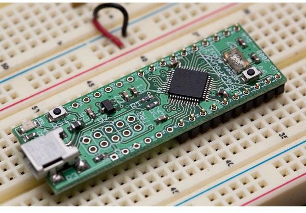
The class uses an AVR32 microcontroller from Atmel, specifically, the UC3B type controller AT32UC3B1256, mounted on a small development board based on the successor of the copper board developed by StackFoundry, called bronze_v2, developed by Daniel Fasnacht.
The Atmel USB chip is a high-performance Atmel 32-bit CPU optimized for small code size: (AVR32UC3B1256: 256KB flash, 32KB RAM, full-speed USB, 60MHz CPU clock, and lots of features like GPIOs, ADC, DAC(PWM), Timers, USART, I2C and even a 16-bit stereo audio out.
The two really cool things about this device are:
- it is supported by GCC (=GNU C compiler), so you can you the entire open-source GNU toolchain with Eclipse IDE (=integrated development environment) to program it (no cygwin needed either!).
- the chip has a built-in programmer factory-programmed into its flash memory, which allows you to program even a blank + bare chip without any programming device, using the standard DFU (=Device Firmware Update) protocol, which is mostly known from smart-phones otherwise.
Tool installation
Additional development tool installation guides are available from https://neuromorphs.net/nm/wiki/2011/usb11, but do not install the Atmel tools from Atmel; use the downloads as instructed below from attachments to this page.
To communicate with the copper|bronze USB board, we use Python (the python tutorial) and pyusb (pyusb tutorial). Underlying pyusb is the USB driver which is libusb. Again, see https://neuromorphs.net/nm/wiki/2011/usb11 for detailed instructions to develop code, program the controller's flash, and communicate by USB to the board. You will be confused by a large number of versions of these tools if you try to install without following these instructions. For faster download, some of the necessary files are below.
The tool setup is quite lengthy since you need to set up
- the development tools,
- the example project,
- the USB device driver,
- the firmware DFU programming tools,
- the host side python environment
- and the python USB package.
You will need to follow the following steps, referring to https://neuromorphs.net/nm/wiki/2011/usb11 for more details.
- Install the AVR32 Studio IDE using the IDE from the attachments below. Do NOT install the latest AVR-Studio 5.1 from Atmel. We will be using avr32-studio 2.7x.
- Start AVR32 Studio (don't install the USB drivers it offers to install). Import Daniel’s usb-rgb-ldr example project (see attachments below) into AVR32 Studio using the File/Import…/General/Existing projects into workspace option. Use all defaults for project import.
- In AVR32 Studio, build the project with ctl-B or using Project/Build all. If there are build errors, check that the device is set properly. Right click on the usb-rgb-ldr project in the left explorer pane, select Properties, select C/C++ Build/Settings, then scroll the panels using the right arrow button to the right to the hidden one called MCU Settings. Select the AT32UC3B1256 from the list of UC3 devices. This should fix the build problems. If not, re-import the project, making sure you are selecting the folder usb-rgb-ldr that contains the .cproject file; this folder is the eclipse project.
- Install the Device Firmware Update (DFU) tool called Flip. This installs the command line tool batchisp used by AVR32 Studio when you run a “target” to program the board. Restart AVR32 Studio after installing Flip.
- Plug in a
'bronze' or'copper' board - but don't install a driver yet. - In windows, install the libusb USB driver by downloading the archive, extracting it, and running the bin/inf-wizard.exe program to generate the driver and install it. Note you will need to eventually generate and install two libusb driver instances: one for the device in DFU state and the other running your application. These will have different PID (Product Identifcation) numbers.
- In AVR32 Studio, make a new target (lower right corner window) that programs the board using the USB bootloader DFU. Let's call it “DFU”. In the DFU details choose the USB DFU target and the AT32UC3B1256 chip.
- Put the device in DFU state by holding down the RST (reset) and DFU buttons, then releasing RST, and then finally releasing the DFU button. The device is now ready for programming.
- Program the sample copper board with usb-rgb-ldr. Select the usb-rgb-ldr.elf binary device file in the project's Debug folder. Choose to Execute after programming and also Erase before programming. If you get a complaint about a missing batchisp you haven't installed Flip or batchisp is not on your path. If you installed Flip, maybe you forgot to restart AVR32 Studio. You will not see anything happen yet because the device needs to communicate over USB. But if you look in the console for programming you should see success there, along with a warning about overlapping code segments, which you can ignore. To find the console output from batchisp, hunt around on the top right of the Console tab for the icon that looks like a monitor and select from this pulldown the appropriate console.
- Install python and pyusb, so that you can run the python rainbow.py script. We are using python 2.6; in general you cannot use a different version of python.
- Run rainbow.py on the host. The firmware usb-rgb-ldr runs on the sample copper board. With LDR and RGB LEDs added you will be able to see it working; you can use the sample board to test this. To run rainbow, you can either start the python shell, open rainbow.py, and run it from the python editor (IDLE). Alternatively, you can import the rainbow project to eclipse (in this case as a python project) and set up the python interpreter environment to use your installed python; point the interpreter to python.exe in your python26 installation (by default in c:\python26). Then you have the comfort of running rainbow from within eclipse. If you don't have your avr32 plugged in, or have not programmed it, rainbow will not be able to open the usb device with VENDOR = 0x03eb and PRODUCT = 0x2300, and you will see a (cryptic) message something like AttributeError: 'NoneType' object has no attribute.'open'. Good luck!
Starting a new project
You might want to start with an existing sample project. Then you will run into the problem that there is no “user_board.h” for the AVR32 board. Please see the sample code below for sample header files for the AVR32 bronze board.
Documentation
See the following documentation for more information. Remember we are using the AT32UC3B1256.
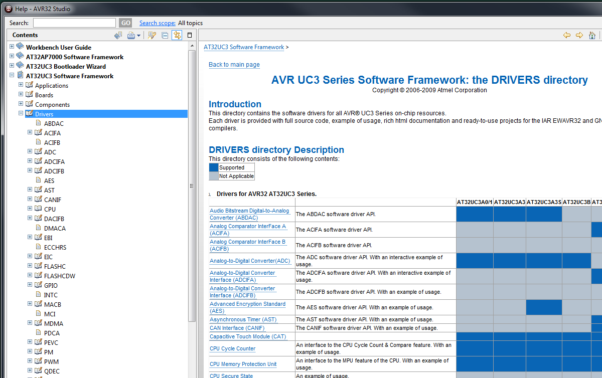
Within AVR32Studio, use the Help/Help Contents menu to open the built-in help. Then, within the document, navigate to the AT32UC3 Software Framework/Drivers section; there you will see sections for each peripheral, as illustrated below.
Using eclipse
- See this post for useful keyboard shortcuts in eclipse, particularly ctl-shift-l for the popup showing you shortcuts.
See also the attached reference documents.
- AVR32 datasheet - for using peripherals and electrical specifications.
- AVR32 technical reference - for architecture and instruction set.
- AVR32 software framework guide - introduces the complex software framework. See this nice video introduction from Jesse Hunter.
- Getting started with GCC for the AVR32 - helpful for understanding gcc with AVR32 and seeing what optimization does and what builtin single cycle instruction directives are available.
- AVR32 bootloader reference - about the DFU=Device Firmware Update protocol and trampoline code needed to bypass it for your applications.
- Copper board schematic - the schematic of the original prototyping board.
- Copper board BOM=Bill Of Materials: list of components on the copper board.
- Bronze board schematics and layout - older board used in 2012
- Bronze board assembly guide - older board used in 2012
Important note for (old) copper board DFU
You may find that the copper board does not properly enter its application program and always boots up after reset or power on in “DFU” mode (Device Firmware Update mode). That happens because by default the PUER (Pullup Enable Register) does not enable the GPIO internal pullup resistors of 5-25k (nominally 12k) Ohms on the port pins, and the leftover internal pullup resistance on pin PA13 is not sufficiently small to pull the logic level to Vdd, so the AVR32 thinks it should go into DFU mode. You can easily correct this by soldering on the copper board or wiring on the breadboard a resistor of 10-20k Ohms from PA13=pin 25 to 3.3V Vdd. Then on reset PA13 will be held high and the application program will start. The bronze board has this pullup resistor added on the board.
Example firmware
- user_board.h - header file for bronze board, defines some useful pins - new in 2013
- usb-rgb-ldr - firmware example RGB LED + LDR project
- rainbow.zip - host side python code for usb-rgb-ldr firmware
- GPIO example program that toggles pins. Has lots of startup code.
- RGB LED example program that shows how to use PWM outputs
- ADC example program that reads ADC values and uses them to set RGB LED output
- boot.tar - trampoline code that bounces your program over the DFU bootloader (already included in example project, you probably won't need this)
Installers
For installers, please see the FTP download area at ftp://ftp.ini.uzh.ch/pub/INI/users/tobi/dig/uc/
Windows
There are reports that the downloads below are corrupted and that install of AVR32 studio cannot be completed.
- AVR32-Studio IDE Installer - this is the main IDE for code development
- Flip installer - installs the batchisp command line program used by AVR32-Studio to program the controller using DFU
- libusb for windows - the USB driver to talk to the board
- python for windows - we talk to the board from the PC using a python program
- pyusb installer - python uses this package to talk to USB
- Java Runtime Environment (JRE) installer - needed to run the IDE


