Table of Contents
SMD bronze_V2 surfance mount board assembly
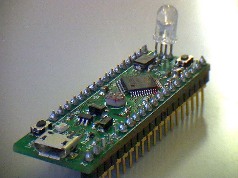
This year in lab_2 we will solder a USB-microcontroller board named bronze_v2. Bronze has includes Red/Green/Blue LED and LDR (=Light Dependent Resistor), and uses a USB host plug so you can plug it directly into a computer, or use a USB extension cable to put it somewhere else.
To assemble your bronze PCB you will arrange an appointment at the Institute of Neuroinformatics (http://www.ini.uzh.ch), which is located at UZH (Irchel or Milchbuck tram stop), building 55, floor G, electronics workshop, directions here.
Please follow the detailed steps below. Videos will help you see exactly how to do various steps.
Parts
Parts are kept in the ring folder in transparent envelopes. Each envelope is labeled with the bronze board part designator, e.g. R5, D1, etc.
Please put the parts back immediately after taking them out. And make sure that parts go back inside the labeled bag for each part!!!!!!!
Tools
Your setup for assembling SMD prototypes consists of
- a soldering iron with large and fine tips, and maybe a heated soldering talon. Always wipe your iron on a damp sponge before using. Resist the temptation to use a super fine tip. You will just make life hard for yourself. There is almost never a need for the iron to touch only a single pin, since solder likes to stick to the metal pins and pads and not to the board.
- a magnifier, very useful for inspecting solder joints from different angles. Your solder joints should be shiny and bright and form a clear wedge from the pad (on the board) to the pin (on the part). We often see beginners only heat the pin and not the pad, resulting in all the solder sticking to the pin and none to the board.
- a solder paste dispenser
' and'rosin-core solder wire. Both are useful. - solder wick, which is handy for removing excess solder and solder bridges which short between pins.
- liquid solder flux, which is handy for deoxidizing metal better and helps the solder to flow.
- tweezers, essential for handling parts.
- pins, which are handy for moving parts around and scraping out gunk.
- razor knife, which is used for cutting board traces.
Step 1: Getting Started with the 5V rail and the PWR LED
Before starting with this step, watch this video: http://youtu.be/4_XqoapZ5Qk to see in general how to solder small 2 pin parts. <html> <iframe width=“420” height=“315” src=“http://www.youtube.com/embed/4_XqoapZ5Qk” frameborder=“0” allowfullscreen></iframe> </html>
In this video you the assembly and testing of some components on the bronze board which are simple to solder is shown.
On the bronze board, start with soldering the following
- D1 - the power LED. Check the polarity carefully. The blue LED needs the fat gold wire on the right side - the C cathode/minus side.
- R5 - the power LED limiting resistor: 1k Ohms.
- P3 - the male type A micro USB connector. Note the micro USB connector on bronze_v2 is different than in the images below.
- L1 - Ferrite Bead with 600 Ohm @ 100MHz and 150 mOhm DC to block noise in VBUS out of the 5V coming from the USB host.
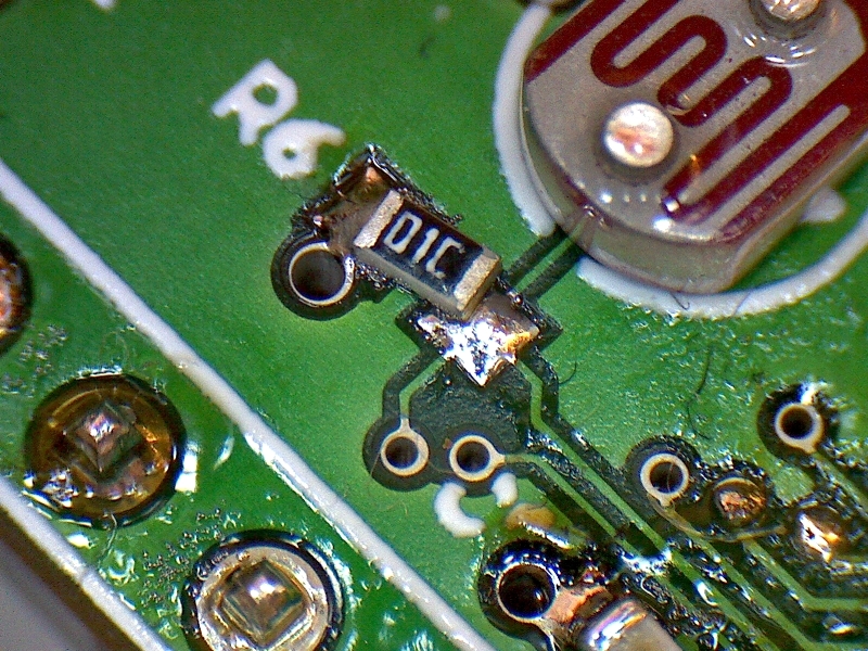
Your soldering should end up shiny and bright and should clearly flow up from the pad onto the pin of the part. The image below shows a resistor that was not soldered correctly. Do you see how the solder has not flowed up onto one pin of the resistor?
When you solder the USB connector:
- Solder the through-hole holding pins first, the the SMD pads.
- When you solder the holding pins, try to align the USB connector properly, and check that the pins and pads are properly aligned on the top side before trying to solder them.
- To solder the SMD pads, put down some flux on the pads, then take a bit of solder on the tip of the flat solder iron and gently brush across the pins.
- Do not push too hard or you will bend the pins.
- Be careful not to melt the plastic of the micro USB connector.
- Inspect the pins under the microscope to make sure they are all soldered nicely. It is easy to put too much solder, just start with a little bit and then add some more only if needed!
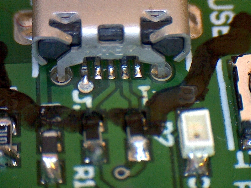
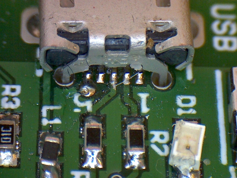
- Below is an example of a micro USB header that is not properly soldered. Note how the left pin is not soldered.
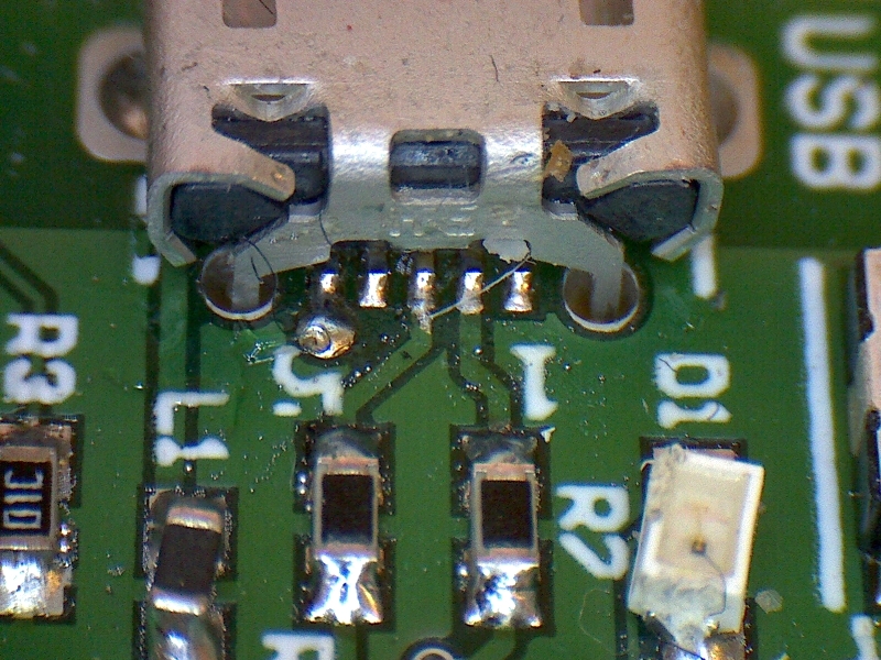
A properly soldered USB header is next:
After all these components are soldered, the blue LED should go on once you connect your board to a computer. You should start however, by connecting the board to the current-limited power supply (limited to about 100mA) with the USB micro plug on it. That way, if you have a short, you will not trip the overload protection on the laptop USB hub.
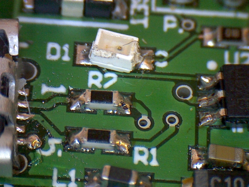
The orientation of the LED is shown here; the dot on the LED points away from the USB connector and the right side is the cathode (negative) side of the LED:
When you solder the USB connector, make sure not to short the metal case to any of the pins. It should end up looking like this:
Check 1
The power LED should light up when you plug it into the USB cable connected to the current-limited power supply and the board should consume less than 20mA.
If you don't have this current-limited supply, then the power LED should light up when you plug in the board to a computer, and you should check that the voltage across C2 is within 5V +/- 5%.
Step 2: Soldering the 3.3V rail stuff
Next we'll solder the voltage regulator that makes 3.3V from the USB 5V VBUS and some power supply bypass capacitors.
Solder:
- U2 - the voltage regulator 3.3V.
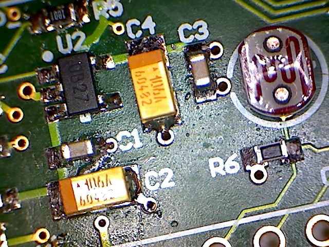
- C1, C2, C3, C4 - power supply bypass caps. Note that two of these (C1 and C3) are 100nF ceramic chip caps and two (C2 and C4) are 10uF polarized [http://en.wikipedia.org/wiki/Tantalum_capacitor tantalum chip capacitors]. Note that 100nF is the same as 0.1uF if you can't find the part. The positive side of the tantalum capacitor is marked with a bar. The image below shows the orientation of the tantalum capacitors. The caps should be placed so the bar is on the bottom side of the U printed on the PCB:
Check 2
Measure the 3.3V rail voltage over C3 or C4. The voltage must be within 3.3V +/- 5%. And again, the current-limited supply should not consume more than about 20mA.
Step 3: solder the difficult parts
Before soldering the next components, watch this video: http://youtu.be/uPbjyeJypcg <html> <iframe width=“420” height=“315” src=“http://www.youtube.com/embed/uPbjyeJypcg” frameborder=“0” allowfullscreen></iframe> </html>
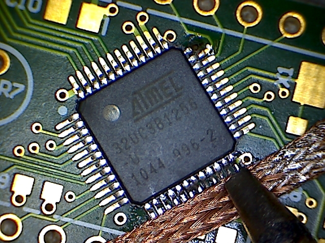
When soldering the AVR32, in case you create bridges between the microcontroller pins: * make sure that they don't have to be there: Check with a blank PCB whether the two pins are connected by a trace directly in between. On the bronze board, no pins are shorted by direct traces between the pins. * Remove extra solder to clear the bridge:
- Use a soldering iron with a big flat tip
- Use the 0.6mm solder wick
- Cut off the used parts of the wick and use the fresh end of the wick to minimize the energy being pulled away by the wick
Here's what it looks like:
Now it is time to solder:
- U1 - our USB microcontroller AT32UC3B1256
- X1 - The 12MHz crystal
When handling U1, be careful not to bend any of the pins. If you drop U1 on a hard surface the pins will almost always be bent on the corner and it is very difficult to straighten them. Be careful bending the pins in any case; they are brittle and will break off easily.
When you place the AVR32 on the board, make sure the pin 1 dot points as shown towards the USB connector. You can also see a pin 1 dot on the PCB. Someone once soldered the part at 90 degree angle. It is possible to remove the AVR32 but requires multiple soldering irons and also the use of 'ChipQuik', or else a hot air pencil. And it is not so easy. So make sure the orientation is correct…
When you solder U1, make absolutely certain that the part is lined up properly on all four sides after you solder only one corner pin. If the alignment is not correct, fix it before soldering any other pins. Once you solder one corner correctly, solder the opposite corner. If everything is lined up properly, then solder one of the sides that has no solder. Now the rest should be easy. Do not mash the pins, a gentle touch of the soldering iron is all that is needed. If you bend the pin while soldering it is very hard to get it back on top of the pad. To solder the pins, apply a bit of thin wire solder to the iron tip and get it to flow onto the pins and pads. A bit of liquid flux applied to the line of pads helps in this case quite a bit. Usually only a single bit of solder, or maybe two, is enough for all the pins on one side.
Step 4: Other parts and don't forget the zero ohm resistor on the back side
If you are confident that U1 and X1 have been soldered correctly, you can solder the remaining (easy) components. Refer to the schematic for values. All parts are in the folder of parts labeled by part number.
- C5 & C6 - the 22pF crystal load capacitors
- R3 - 10kOhm TCK pullup resistor
- R1 & R2 - 39Ohm USB data lines series resistors
- RESET & DFU - the two micro switches
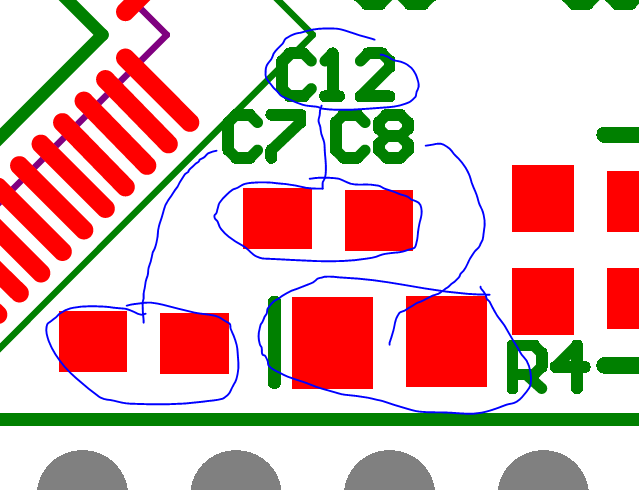
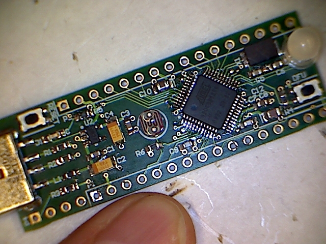
- Any other capacitors or resistors except the LDR (= Light Dependent Resistor, the thing with the curly pattern on its face, R7) and the RGB LED (D2, = Red/Green/Blue Light Emitting Diode). Note that C7, C8, and C12 are arranged as shown below; do not confuse R4 (the vertically aligned resistor next to the switch) with one of the capacitors. C12 is the top of the triangle, C7 is lower left, and C8 is lower right.
There is one component on the back side of the board, L2, which should just be a shorting jumper. Solder a 'zero ohm resistor' (a jumper). This connection isolates the AVR analog supply voltage. If you forget it nothing will work!
Your board should now look like this (except you will not have the LDR or RGB LED):
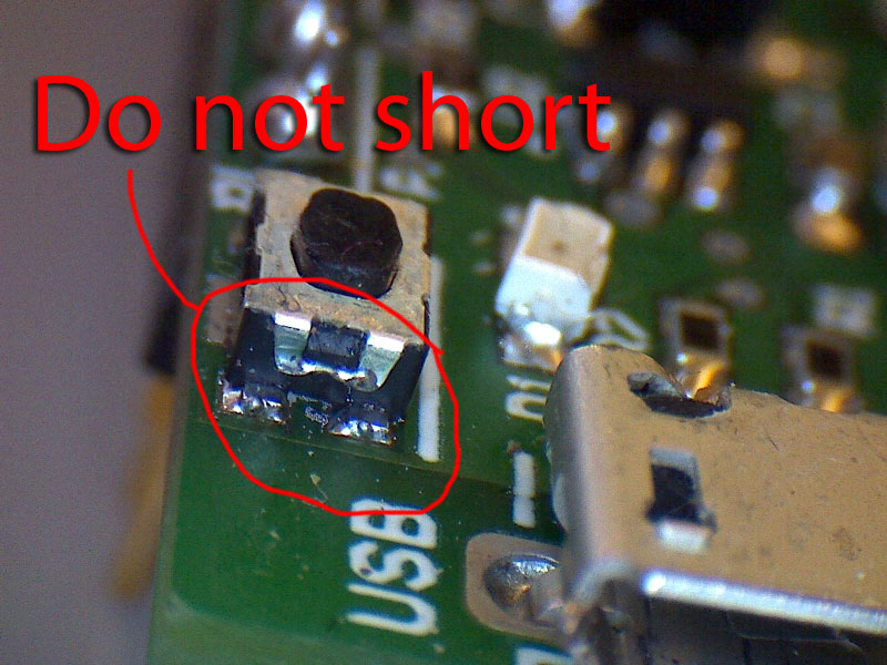
When you solder the button switches, make sure not to short any of the pins or the case:
Check 3a: Visual inspection
Look at your board under the high power microscope. Look especially between the pins. You should not have leftover solder balls! If there are too many they will cause a short - maybe not today but later on. In any case, your solder joints should be shiny and clean and clearly weld the pins to the pads with nice wedges.
Check 3b: Electrical test
First, plug your board into the current-limited supply with the USB cable on it. If your board draws too much current the voltage will drop. A working board draws <40mA @5V. If your board draws too much power you must find the short(s) and fix it/them.
Next, after plugging in the board to a computer, check all rail voltages again:
| Measurement Site | Nominal Value | ||
| C1 or C2 | 5.0V +/- 5% | ||
| C3 or C4 | 3.3V +/- 5% | ||
| C7 or C8 | 1.8V +/- 5% |
If any of the voltages are out of range disconnect the board immediately and start visual inspection, and have someone else look at the board.
Check 4a
If you have an oscilloscope, let's check the oscillator: * Attach a wire to some GND pin. * Connect the scope ground clamp to the wire * Check the signal on C5 or C6, on the signal side, not the ground side. * You should see a (more or less sinusoidal) 12MHz signal with about 1Vpp amplitude.
Check 4b
Connect your board to a Windows computer and in the Device Manager you should see the AVR32 USB DFU device show up (if you installed the driver earlier).
Or, connect your board to a Linux computer, then run the command lsusb in a shell.
Besides other devices you should see:
Bus ??? Device ???: ID 03eb:2ff6 Atmel Corp.
Check 5b
To get further information on what Linux found out about the device, run sudo lsusb -d 03eb:2ff6 -v
You should get this: <code>
Bus ??? Device ???: ID 03eb:2ff6 Atmel Corp. Device Descriptor:
bLength                18
bDescriptorType         1
bcdUSB               2.00
bDeviceClass            0 (Defined at Interface level)
bDeviceSubClass         0
bDeviceProtocol         0
bMaxPacketSize0        64
idVendor           0x03eb Atmel Corp.
idProduct          0x2ff6
bcdDevice           10.00
iManufacturer           1 ATMEL
iProduct                2 AT32UC3B DFU
iSerial                 3 1.0.2
bNumConfigurations      1
Configuration Descriptor:
  bLength                 9
  bDescriptorType         2
  wTotalLength           27
  bNumInterfaces          1
  bConfigurationValue     1
  iConfiguration          0
  bmAttributes         0xc0
    Self Powered
  MaxPower              100mA
  Interface Descriptor:
    bLength                 9
    bDescriptorType         4
    bInterfaceNumber        0
    bAlternateSetting       0
    bNumEndpoints           0
    bInterfaceClass       254 Application Specific Interface
    bInterfaceSubClass      1 Device Firmware Update
    bInterfaceProtocol      2
    iInterface              0
    Device Firmware Upgrade Interface Descriptor:
      bLength                             9
      bDescriptorType                    33
      bmAttributes                       15
        Will Detach
        Manifestation Tolerant
        Upload Supported
        Download Supported
      wDetachTimeout                      0 milliseconds
      wTransferSize                   65535 bytes
      bcdDFUVersion                   1.01
Device Status: 0x0001
Self Powered
<\code>
Step 6: Pin headers
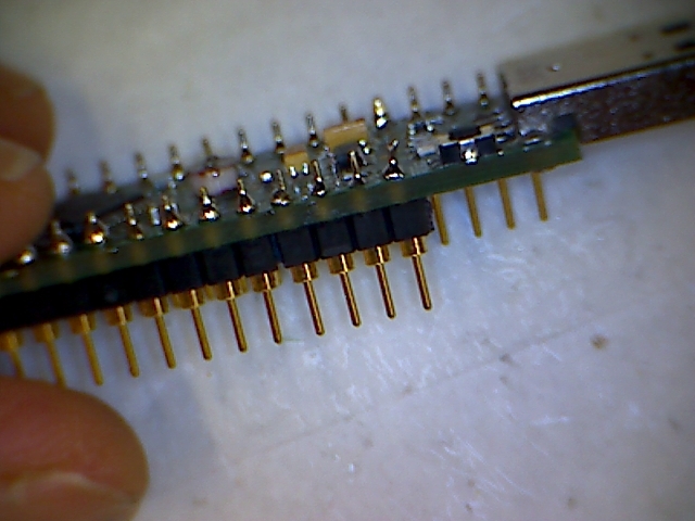
Now solder the 2×16 pin round pin gold plated headers into the bottom of the board to allow you to plug the bronze board into a solderless breadboard, as shown below. (Someone actually soldered the pins to the wrong side once.) Solder the thin pins from the bottom into the board so that the thick tough part sticks out. You will need to cut apart some pieces. Make sure the pins are nicely vertical and properly aligned so that you can plug the bronze board into the solderless breadboard later. Do this by solderining just one pin at the end of the strip and while the solder is hot you can make the pins at 90 degrees right angle. Then you can solder the rest of the pins.
Step 7: LDR and RGB LED
Finally, you can solder the LDR and RGB LED if you want to run this test.
The LDR is not polarized.
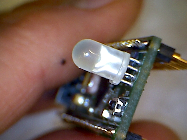
The RGB LED has one ground cathode pin and 3 positive anode pins, one for each color. It is oriented as shown below, with the flat side of the LED to right right when you look at the board from the end; the long wire of the RGB LED is third from the left:
You made it till down here? Congratulations! Your board passed all tests that do not require a test-firmware to be flashed…
Your board will end up looking like this:
Step 8: Clean the board
Use the flux remover spray and brush to clean off flux and solder balls. You can blow the board dry with the pressurized air. Don't use too much flux remover because it is expensive.
Documentation
See the following documentation for more information. Remember we are using the AT32UC3B1256 and assembling the bronze_v2 board.
Further info on the original copper board: http://store.stackfoundry.com/dev-tools/copper-avr32-stick.html
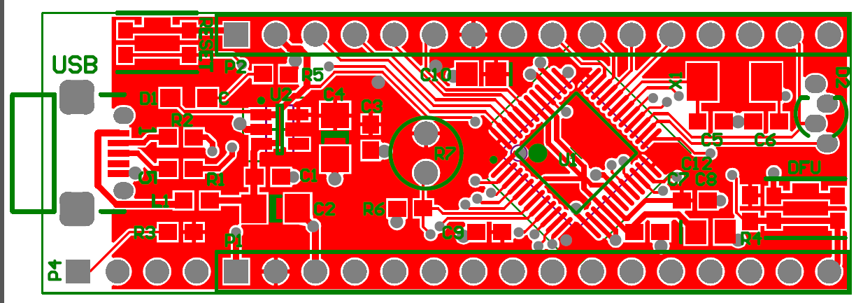
- bronze_v2_pcb_top.pdf - top layout showing wiring
- Copper board schematic - the schematic of the original prototyping board.
- Copper board BOM=Bill Of Materials: list of components on the copper board.
- AVR32 datasheet - for using peripherals and electrical specifications.
