Table of Contents
Lab 3
Note these instructions are somewhat outdated by switch to Arduino Nano in 2014.
In this exercise, let's build a microphone preamp on the protoboard, acquire the audio signals on the AVR32 using the ADC, process the auditory signal to measure the RMS power (sound volume), and then use the average sound volume over the past few hundred ms of time to set the position of a servo motor. In lab_4 you will turn your prototype into a PCB schematic.
To achieve this, we need to interface to and control a servo motor and build a microphone preamplifier. Let's use the protoboard for both of these.
Steps for this exercise
If you finally have to give up for lack of time or success, a solution will be revealed in two weeks. Follow the following general steps to complete this exercise:
- Build the microphone preamplifier on the solderless breadboard to amplifier the microphone signal. One person can do this while the others in a group can work on the next parts.
- Sketch an outline (flow diagram) of your application, including the AD conversion, the servo control, the signal processing. What peripherals (AVR32 Software Framework Drivers) will you need?
- Start your AVR32 project (see below) by cloning the usb-rgb-ldr project.
- Adapt the PWM code to control the servo.
- Adapt the ADC code to read the microphone preamp output.
- Write the DSP (digital signal processing) code to process the ADC samples to control the servo position.
- Adapt the USB code on the device and host (rainbow.py) to debug your code.
- Document your code with comments.
- Demonstrate your working system to Tobi and send your project by zip (or .7z) archive attachment email to Tobi Delbruck.
Background information
- uc for microcontroller software tools and example firmware setup
- servos - information about RC hobby servo motors
- microphones - information about electret microphones
- breadboard - solderless breadboard
- micpreamp - microphone preamplifier
Starting AVR32 Project
Let's copy the usb-rgb-ldr project to a new one called mic-servo, following the instructions given at http://support.atmel.no/bin/customer.exe?=&action=viewKbEntry&id=308.
Let's modify this project so that we produce a suitable servo output signal in response to the sampled sounds from the ADC.
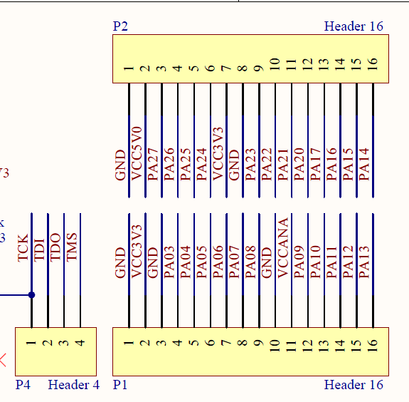
AVR32 board pin headers
PWM - Pulse Width Modulation
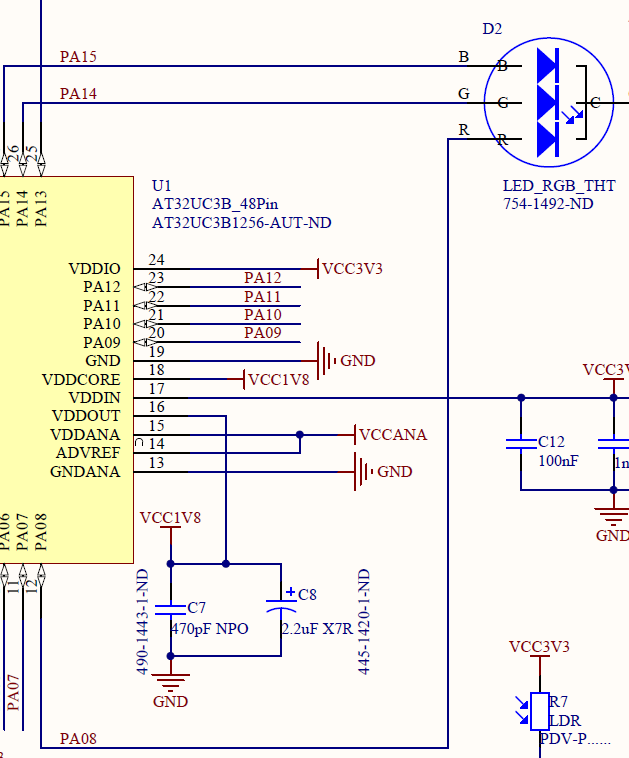
- Decide on a new PWM output pin for your servo output pulses. Looking at the bronze or copper schematic and the AVR32 datasheet, we see that the bronze board hard-wires PA8 to the red LED Anode, PA14 to the green anode, and PA15 to the blue anode. These are pins 12, 26 and 27 on the AT32UC3.
Let's use PWM[6]=PA19=pin 31 for the servo PWM output. Ahh, but we can't, can we? That pin can only be used for GPIO or PWM if we don't use a crystal oscillator, so it's already used up, just like PA18. We see that an alternate location for PWM[6] is PA22 on pin 34. This one is available, so let's use it. In fact it's the default Function A alternate to GPIO22 for the pin, according to table 4.1 in the datasheet on page 8.
We enable this “Function A” mode for PA22 with
#define SERVO_PIN			AVR32_PWM_6_0_PIN
#define SERVO_PWM_FUNCTION	AVR32_PWM_6_0_FUNCTION
	gpio_enable_module_pin(SERVO_PIN, SERVO_PWM_FUNCTION);
- To main.c, add code to use PWM channel 6 cloned from one of the RGB LED outputs:
#define B_PWM_PIN			AVR32_PWM_4_0_PIN
#define B_PWM_FUNCTION		AVR32_PWM_4_0_FUNCTION
#define B_PWM_CHANNEL_ID	4
- Increase the number of channels to 4 from what is there now:
static avr32_pwm_channel_t pwm_channel[3];
static unsigned int channel_id[3];
- Modify the init_pwm() function to initialize the servo PWM output. To do this, study how the PWM is set up and change it so that the PWM output frequency is ~100Hz. You may want to use an oscilloscope to examine the RGB PWM output. The usb-rgb-led program has a PWM LED frequency of 4kHz. If you examine init_clock() you will see that the core clock frequency is 33MHz.
gpio_enable_module_pin(B_PWM_PIN, B_PWM_FUNCTION);
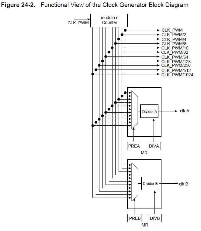
In pwm_init(), the PWM controller is configured for certain choices of prescaler and divider. These choices determine the clocks available to individual PWM channels:
	// PWM controller configuration.
	pwm_opt.diva = AVR32_PWM_DIVA_CLK_OFF; // no divider
	pwm_opt.divb = AVR32_PWM_DIVB_CLK_OFF;
	pwm_opt.prea = AVR32_PWM_PREA_MCK; // no prescaler for div a or b
	pwm_opt.preb = AVR32_PWM_PREB_MCK;
You also need to initialize the servo PWM channel to use one of these available clock sources, to end up with a period of about 100Hz. An existing LED channel looks like this:
		pwm_channel[c].CMR.calg = PWM_MODE_LEFT_ALIGNED; // Channel mode.
		pwm_channel[c].CMR.cpol = PWM_POLARITY_HIGH; // Channel polarity.
		pwm_channel[c].CMR.cpd = PWM_UPDATE_DUTY; // Not used the first time.
		pwm_channel[c].CMR.cpre = AVR32_PWM_CPRE_MCK_DIV_2; // Channel prescaler.
		pwm_channel[c].cdty = 0; // Channel duty cycle, should be < CPRD.
		pwm_channel[c].cprd = (256 << TTT); // Channel period.
		pwm_channel[c].cupd = 0; // Channel update is not used here.
The prescaler is what you need to change; it is set to 2 above and you need to increase it to reduce the servo pulse frequency. The 20 bit cdty field sets the duty cycle and the 20 bit cprd field sets the period, in units of the PWM channel clock period, which is set by the clock you choose with the cpre field.
- Write a function setPWMWidth(int us) that sets the PWM output pulse width to the supplied value in us. Then 1500us will be the center servo position and 1000 and 2000 the extremes. You don't need to be exact about this since the PWM has a limited clock source division and prescaler choice.
/** Argument, pulse width in us
 *
 */
void setServoPWUs(U16 us) {
	pwm_channel[cServo].cdty = .... // you need to fill this in
	pwm_channel_init(channel_id[cServo], &pwm_channel[cServo]);
}
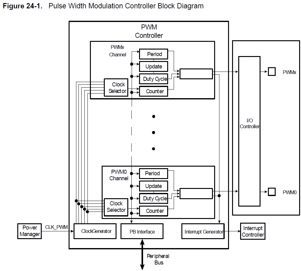
To see what this all means, look at the following block diagram, from the datasheet. The PWM channels all share a common ClockGenerator, but each have their own ClockSelector. They each also have registers Period, Update, DutyCycle, and Counter. Period is a 20 bit value that determines the pulse period. DutyCycle, which must be smaller than Period, determines the duty cycle. Update is a register that you load and on the next cycle the duty cycle contents are replaced. This way, no funny partial cycles will occur. Counter is a read-only register that lets you examine the current counter value.
You can try it out with a servo motor, using the USB VBUS +5V to power the servo and a long pin header to connect to the protoboard and the servo, following the guide above according to your servo type. Use a 10000uF electrolytic capacitor and a blocking 1N4007 diode to bypass the VBUS to ground on the protoboard or you will get a huge amount of motor noise appearing in VBUS! You will end up with about 4V to power the servo which is on the low side but it should still work.
To test the servo code, modify firmware so that the LED PWM value sent from the host now sets the servo position as well. See the function device_task(). There the 4-byte word from the host is used to set the RGB LED PWM outputs. The RGB values range from 0-255. You can also use one of the colors to set the servo position. Multiply the color value by 4 («2) and add 1000 to get a range from 1000 to 2000 us.
Sampling audio and signal processing
We've already built the microphone preamp circuit on the protoboard, using a JEFT microphone (datasheet), resistors, capacitors, and an LM324N quad opamp.
Now let's write a main loop that samples the microphone input, computes the average mean square sound level, low pass filters it, and sets the servo according to this sound volume. Ideally you would sample at a regular rate set by a timer interrupt, but here we do everything in a polled way because it is much simpler to implement. We could use software delays to slow things down enough.
The pseudo code for the signal processing should go as follows:
- Get an ADC sample
- Update the fading average sample value. We need to subtract this from the sample to get the deviation from the mean.
- Compute the square of the difference of the sample from the fading average.
- Update the fading average mean square value.
- Use this value to set the servo position.
Remember that you only have fixed point hardware. The ADC samples are 10 bits expressed as the 10 lsbs of a U16 value. You can add up a lot of 10 bit values in a 32 bit value.
Debugging by GPIO toggling
You may notice certain calls such as the bit banger:
gpio_local_tgl_gpio_pin(AVR32_PIN_PA11);
This call toggles PA11. You can monitor PA11 on an oscilloscope to see that the program gets to this line of code and how often/fast it does this.
Converting the microphone input
Referring again to the AVR32 datasheet in section 4.2.1 (Multiplexed signals), we see that the 6 ADC inputs AD[X] on our 48 pin version of the AT32UC3B1256 are on PA 3,4,5,6,7,8. Let's use one not used by the bronze board LDR, say AD[1], which is on PA04 which is pin 8 on the chip package. Looking at the copper or bronze schematic, we can find this pin on the board. Here we'll use the copper board, where the corresponding PA04 pin is on the bottom row 5th from the left end.
Let's modify the usb-rgb-ldr program to use this other ADC channel instead of the one connected to the LDR. (We won't worry about putting the ADC sampling in a timer interrupt routine for now.) Just before init_adc(), you see how the ADC channel is defined; you need to modify this to channel 1:
#define ADC_CHANNEL     0
#define ADC_PIN         AVR32_ADC_AD_0_PIN
#define ADC_FUNCTION    AVR32_ADC_AD_0_FUNCTION
Signal processing
You can put your signal processing at the start of device_task(), before the check for an enumerated device. Move the get_adc_sample() to the start of the function and do your signal processing. You can then use the USB communication part of the function to send back your computed sound volume, to check whether your computations make sense. The usb-rgb-ldr function device_task() sends back ADC samples as shown below:
	// Load the IN endpoint with the contents of the RAM buffer
	if (Is_usb_in_ready(EP_TEMP_IN)) {
		gpio_local_tgl_gpio_pin(AVR32_PIN_PA11);

		// read ADC and store to buffer...:
		U16 adcval = get_adc_value();
		in_buf[0] = 0xDE;
		in_buf[1] = 0xAD;
		in_buf[2] = 0xFF & (adcval >> 8);
		in_buf[3] = 0xFF & (adcval >> 0);
		in_data_length = 4;

		Usb_reset_endpoint_fifo_access(EP_TEMP_IN);
		usb_write_ep_txpacket(EP_TEMP_IN, in_buf, in_data_length, NULL);
		in_data_length = 0;
		Usb_ack_in_ready_send(EP_TEMP_IN);

	}
You should probably do your signal processing using signed and unsigned 32 bit ints (int and unsigned int, or S32 and U32). In complier.h you can find these handy definitions:
typedef signed char             S8 ;  //!< 8-bit signed integer.
typedef unsigned char           U8 ;  //!< 8-bit unsigned integer.
typedef signed short int        S16;  //!< 16-bit signed integer.
typedef unsigned short int      U16;  //!< 16-bit unsigned integer.
typedef signed long int         S32;  //!< 32-bit signed integer.
typedef unsigned long int       U32;  //!< 32-bit unsigned integer.
typedef signed long long int    S64;  //!< 64-bit signed integer.
typedef unsigned long long int  U64;  //!< 64-bit unsigned integer.
typedef float                   F32;  //!< 32-bit floating-point number.
typedef double                  F64;  //!< 64-bit floating-point number.
Some hints for signal processing using fixed point:
- To multiply by a fraction, multiply by the numerator and then divide by the denominator.
- Watch out for overflow, since these will wrap around.
- Divide by zero will not throw any kind of exception.
- Fast divides or multiplies by powers of 2 are done with shift operators « or ».
Advanced Signal Processing with the DSP library
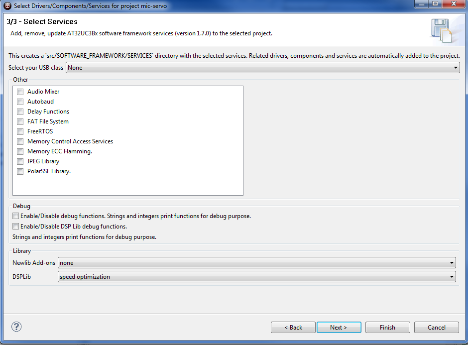
If you are ambitious, you can try using the AVR32 DSP library functions for signal processing. These take advantage of the special instructions in the AVR32UC3B for digital signal processing. To activate the DSP functions, you need to add this module to your project framework, using the menu item Framework. Select an option other than “none” in the services panel for the DSP library as shown below:
And don't forget to add the #include statement at the start of your main.c:
#include "dsp.h"
Using Timer interrupts to Trigger the ADC
You could also try to run the ADC in a timer interrupt to sample at a regular rate. See this example to start. You will need to active the driver for the timer/counter (TC) in the software framework, using the wizard starting from the Framework menu item.
Host side debugging with USB
Let's use the host side to debug the device.
To better work in python, you may want to install in Eclipse the plugin to handle python projects. See this link: http://pydev.org/manual_101_root.html for instructions. Basically in eclipse you use Help/Install new software… and then enter the link from pydev http://pydev.org/updates, then locate your python installation, and accept all the default values. Then you will be able to create a python project in Eclipse and edit and run the python code from eclipse.
On the host side, the python method usbio sends the RGB bytes and takes the byte buffer values sent from the device to reconstruct the 16 bit ADC sample as shown below:
usbiocnt = 0L
def usbio(dh, r, g, b):
    global usbiocnt
    usbiocnt += 1

    dout = array.array('B', [0]*4)

    dout[0] = 0xFF & 0x00
    dout[1] = 0xFF & (r)
    dout[2] = 0xFF & (g)
    dout[3] = 0xFF & (b)

    dh.bulkWrite(EP_OUT, dout.tostring())

    #if usbiocnt % PWMperADC == 0:
    if 1:

        din = dh.bulkRead(EP_IN, 4)
        l = len(din)
        if l != 4:
            print "unexpected bulk read length: %d" % l
        else:
            if usbiocnt % PWMperADC == 0:
                adc( (din[2] << 8) + din[3] )
You can modify this code to pass to the adc method shown below the reconstructed the 32 bit (rather than 16 bit) sound volume value you compute on the device side and print it out in the adc method:
vmax = 1
vmin = 2**16
def adc(v):
    global vmax, vmin
    if v > vmax: vmax = v
    if v < vmin: vmin = v
    if vmax <= vmin: vmin -= 1

    t = time.time() - tstart
    hz = usbiocnt / t

    o = '% 4d Hz  ' % hz
    o += '#' * int( BAR * (v - vmin) / (vmax - vmin) )
    print o
The print methods may be unfamiliar to you. The line “o = '% 4d Hz ' % hz” prints the value of variable hz using 4d format, i.e. 4 place decimal. You can add a field after this on the next line to print your sound volume value.
Remember that python syntax uses indentation to mark code blocks!
Desired Behavior
You demo should end up responding to transient sound volume increases by turning the servo. You can mount an arm and hand on the servo using one of the servo arms and some hot glue to build a “BE QUIET” hand, for instance.
Congratulations if you get all this to work! It seems as though there is a large amount to learn to use a rather simple processor like the AVR32. But if you work with a device like this for a while you will get familiar with it and it will become quite easy to write new functionality.
If you finally have to give up for lack of time or success, see how to make the mic-servo application work.
Documentation
~~DISCUSSION~~
