4. The Sensitivity ListIMPORTANT - DO NOT SKIM READ - THIS IS IMPORTANT |
How Simulation WorksHDL is designed for both simulation (finding out if your implementation will actually work) and synthesis (breaking down your design and mapping it to and implementing it on a device). From the point of view of simulation, we can consider an HDL design to be a collection of processes that are running in parallel. However, because simulation is performed in software on your workstation, there needs to be a way to allow the sequential simulation software process to emulate a parallel one (look at the Gateway introductory lecture slides for a review of computing paradigms and technologies). Simulation is therefore performed by resolving single slices of time one after the other. The state of each signal (1 or 0 in the case of digital circuits) is therefore determined by its past state (or states) and by any relationship between itself and other signals (described by you, the coder or programmer). However, because we wish to have accurate simulations (down to the picosecond time scale) each slice can be extremely fine. This poses a problem, because performing these operations is time consuming (so far you have performed simulations that span approximately 1000ns, this equates to 1,000,000 time slices of 1ps). This may not be an issue for simple circuits, but as the complexity of the design increases, this inefficiency poses a problem (you don't want to have to wait for 20 years for a simulation to finish!). Additionally, the idea of resolving each of the time slices is inefficient because digital signals spend a lot of time in stable states (not changing). This is especially the case for synchronous circuits where the outputs of each D-Type can only change on the rising or falling edge of the clock. To exploit this realisation, the sensitivity list was developed. |
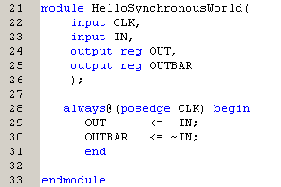
What is the Sensitivity ListThe sensitivity list can be considered the one of the most important parts of any HDL (not just Verilog). Once you get your head around it, everything else tends to fall into place. To explain how it works, the Verilog syntax to implement a D-Type flip-flop is shown below; you will be using this later. |

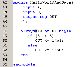
The Sensitivity List and Asynchronous LogicAs stated earlier, you can also use the sensitivity list to surround asynchronous logic. For example, if an AND gate were implemented, the output would only need to be resolved if either of the two inputs changed. Unlike the previous example, this is an example of level sensitivity not edge sensitivity. Unfortunately you cannot mix the two in the same sensitivity list, but this is rarely an issue. |
Signals - Registers and WiresThe last thing that I am going to mention at this point is the 'reg' syntax. This syntax dictates that a signal is a simulation register. However, this does not actually mean that the signal it describes comes from a register within the design (D-Type) although this is often the case. The 'reg' syntax is used whenever a signal is defined within an 'always@(...)' statement, and this is entirely to do with how the simulation works. There are essentially two types of signals in Verilog: wires and registers. Wires derive their value from their connections and do not have an internal state, whereas registers do. This means that a wire only has a state (1 or 0) if it is somehow directly or indirectly (through other wires in different modules), connected to a register. As signals that are assigned values within 'always@(...)' statements are required to hold their values between simulation time slices, they therefore must be registers. This is a complex concept to get your head around, so until you do, remember this simple rule: |
If within a module you have a signal that is on the left hand side of an assignment within an 'always@(...)' statement, then it needs to be defined as a register ('reg'). |