|
Synchronous, or clocked, logic involves the used of registers that hold a signal's state during clock cycles. The output of registers can change only at specific times during the clock cycle, the rising (positive) or falling (negative) edge of the clock. Most digital systems use one or the other. However, some forms of digital memory use both to provide greater performance, an example being Double Data Rate (DDR) RAM. In this laboratory you will only need to implement one; rising or falling edge logic, not both.
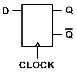
Above is the symbol of a D-Type Flip Flop. You have learnt how to build these from CMOS transistors in last year's Digital Circuits course. On many FPGAs, this component is already made for you. So even though it is made out of transistors on FPGA silicon, for our purposes, D-Type Flip Flops come ready made as a generic resource with our FPGA. The key concept with D-Types is that they will only update their outputs Q and Qbar (the bar means it is always the opposite of Q) on a clock edge (you decide which). Therefore, the input D can jump back and forward between clock edges as much as it likes, but only its value at the clock edge matters.
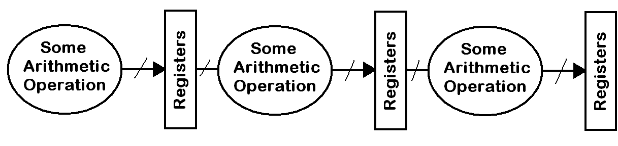
Usually the input to a register is connected to some synchronous logic that performs an arithmetic operation on the inputs to the subsystem. Often the input to the subsystem is the output of a separate set or registers (Dtypes) and hence they act as holding points between operations. This is called a pipeline, and we will cover it more later.
|