|
A state machine is a synchronous system that has memory, in that it knows what it is currently doing, and therefore can decide what it should be doing next by a combination of its current state and incoming stimulus. This is usually represented by two logic blocks, one synchronous, the other asynchronous.

The synchronous logic block is extremely simple, acting akin to a heart through the regulation of the flow of data by latching the states of the OUTPUTS and the Current State upon the rising edge of each clock cycle (you could use the falling edge, but most designers use the rising edge). The asynchronous combinatorial logic block can be considered akin to the state machine's brain, as it determines what the next state is going to be, along with the next value of the OUTPUTS through the combination of the Current State and the values of the INPUTS. This model, illustrated in the above figure, is known as a Moore machine as the outputs depend only on the states (and not on a combination of states and inputs as in the Mealy machine). Moore machines were also referred to as Class 3 finite state machines (FSMs) in your digital circuits 2 course notes.
When describing this behaviour with Verilog code, this can be represented as two always@(...) statements, one clocked (synchronous), the other not (asynchronous). The synchronous block usually also consists of a reset mechanism, and this is the case with all the state machines used in this laboratory. The structure of the this statement is nearly always akin the following code.

The combinatorial code is generally much more complex, as it makes all the decisions regarding the values of the next state as well as the state machine's outputs. The typical way in which a state machine is written in Verilog is through the use of a case statement, where each state is represented as an individual case. Within each case, the value of the next state is determined, which may also be based upon the inputs. An example of a 4-State state machine is give below. Here state transition is only possible if the input 'IN' is held high. This state machine traverses to the next state when 'IN' is high, such that if 'IN' is permanently set to '1' then at each clock cycle the current state will change. Each state is represented by a value from 0 to 3 (2'd0 to 2'd3). Also note the default case that must always be present. In this example it directs the state machine towards state 0. For many designs state 0 is the Idle state (where the machine rests when it has nothing to do), and so this is usually where the default case leads.

This particular state machine could be represented with the following state diagram.
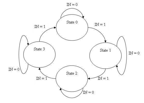
Remember that because of the sequential synchronous logic, the state machine can only follow the arrows on the rising edge of the clock.
|