Table of Contents
Lab 4
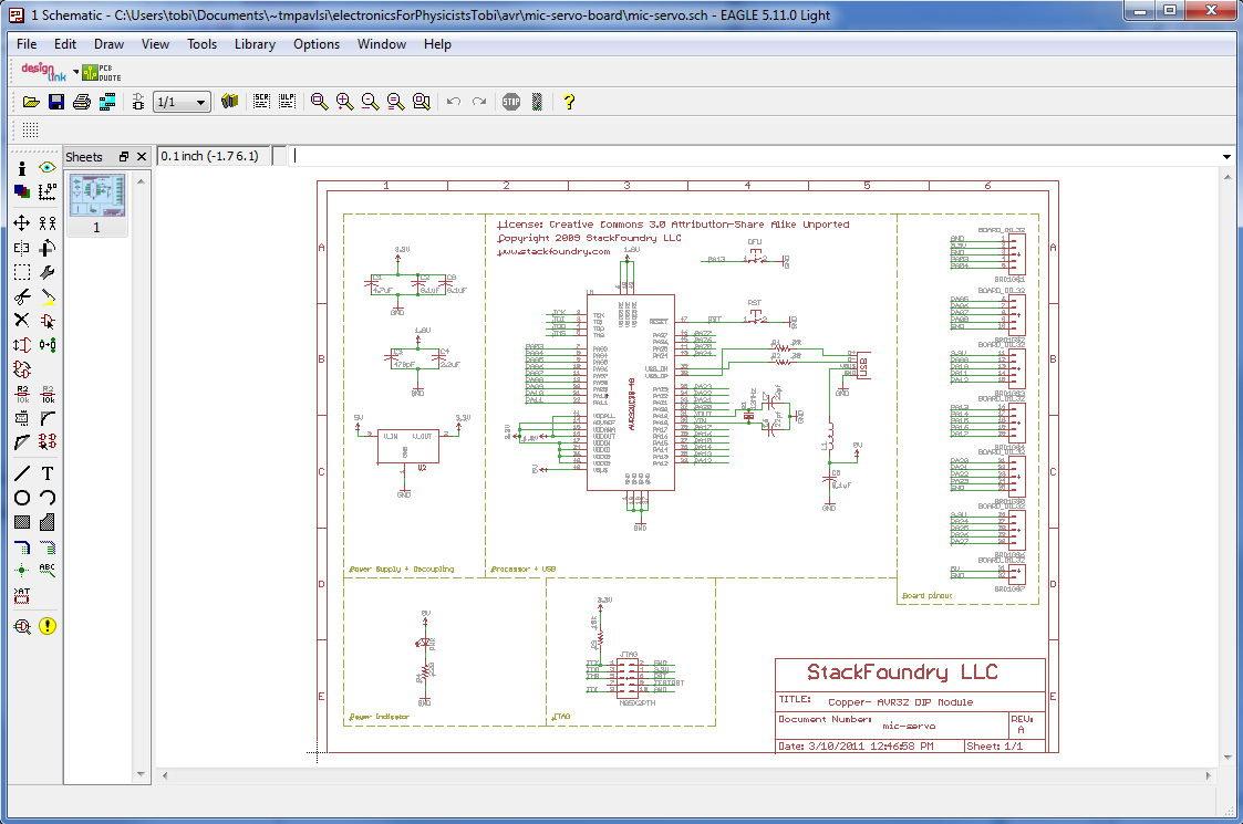
In lab_3 we built a prototype of our microphone-servo board. Now let's design the schematic of our own PCB. We'll draw an Eagle schematic of the microphone amplifier and servo supply / connector from lab 3, using the PCB design tool Eagle. It is not a very super powerful tool but installs very quickly, comes in a freeware version with limited functionality, can run on multiple platforms, and has lots of user-developed parts libraries. In lab_5 after the long Easter break, we'll complete the layout of this board.
This is an individual exercise and each student must complete it on their own laptop.
Preparation (before lab exercise)
- See pcb for the links to download the freeware and limited version of Eagle.
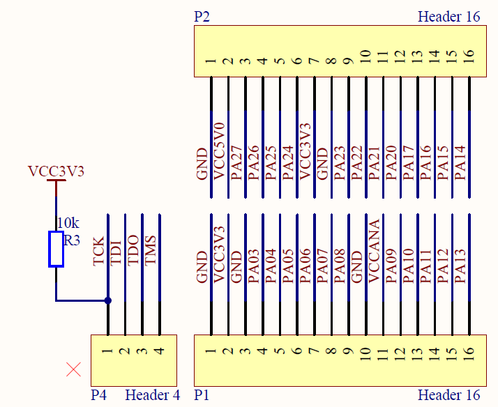
- Download and unpack the copper board Eagle schematic. You can use this copper schematic (PDF version here) to start to build your daughterboard, which will have a female connector to the bronze board, which has slightly different bronze board schematics as a PDF file, as shown below:
Instructions
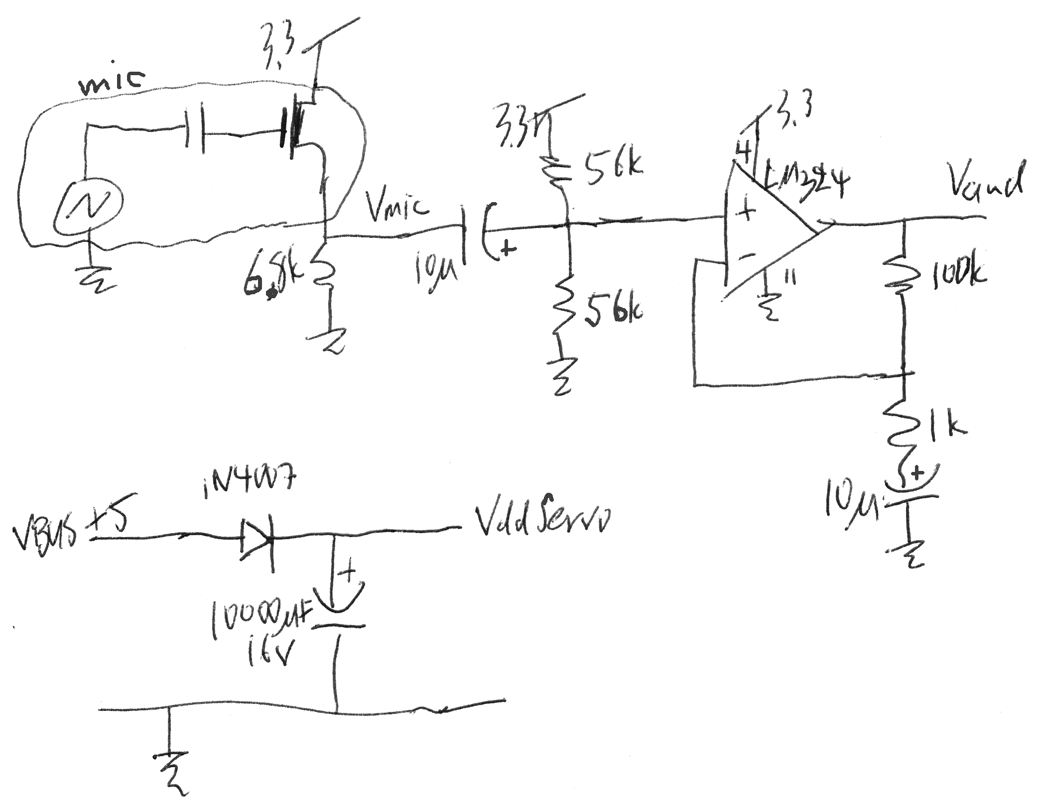
In this exercise we'll draw an Eagle schematic of the microphone amplifier and servo supply / connector from lab_3:
Remember that you actually modified some resistor values in lab_3 to bring the LM324 output more in the middle of it working range (see datasheet extract below).
- Install Eagle - see pcb.
- Open the Eagle dashboard by launching Eagle.
- Save it off to a new schematic called mic-servo.sch.
- Modify your schematic so that the DIL32 header is correct for the bronze board (since we have more of these boards we will use it as the motherboard).
- Add or use gates (symbols) for a resistor, polarized capacitor, LM324 opamp, microphone, and 3 pin header. You have several of these already. Others you will have to either find in the libraries (and thereby learn how to search for parts), or you might have to create a gate symbol.
- Delete the unused symbols.
- Wire up the parts according to the sketch above.
- Ensure your designators and values are correct.
- Place a large label indicating the design name and designer name (your name).
—-
When you are finished with your board schematic, send your schematic file (.sch) to tobi@ini.phys.ethz.ch?subject=micboard schematic for Electronics for Physicists II
Eagle tips
- Use a mouse. A middle click then lets you drag around your view.
- Eagle looks for designs in the directories that you specify in the Control Panel, under Options/Directories.
- Eagle uses a non-conventional way of manipulating objects that takes a bit of getting used to. You cannot drag-select objects for instance. Instead, you select a tool, say “move”, then apply it to individual objects one at a time. Or you can drag the dotted rectangle tool around some stuff and then notice the tip in the bottom toolbar that say you can right-control-drag the group.
- Right click on objects to open the context menu.
- To select an object, look for the little cross in the object and click near that.
- Use the Net tool to draw connections between components, not the Wire tool.
- Many components have hidden power pins, e.g. the LM324. To show these pins so you can wire them up to your Vdd/Gnd, use the Invoke command on the part. Then you will see the hidden power pin 'part' of the component.
- This Eagle Tutorial from Kevin Bolding also shows many more useful tips.
LM324 tip
Data sheets
- LM324 datasheet, SOIC-14 package, Library linear.lbr
- Power Diode datasheet, SMD, http://search.digikey.com/scripts/DkSearch/dksus.dll?Detail&name=641-1170-1-ND, Library DIODE-.lbr, footprint DIODE-20214AA
- Ultra capacitor, http://search.digikey.com/scripts/DkSearch/dksus.dll?Detail&name=P6975-ND. We might use an ultra-cap for the servo power supply bypassing but these are a bit tricky to select. You can find a large (>10k uF) aluminum capacitor instead if you like. Make sure your capacitor can handle >10V.
~~DISCUSSION~~


